Examples of gravity-fed, branched-drain greywater plumbing parts and installations…
The branched-drain greywater system, developed by Art Ludwig, author of Create an Oasis with Greywater (OasisDesign.net), distributes greywater via gravity through pipe installed with a minimum 2% slope (1/4-inch [2-cm] drop per foot [meter] of horizontal pipe), then branches or splits the flow with one or more flow splitters. This way the plumbing and gravity distribute the greywater where you want it to go, so neither you nor a pump need do any extra work.
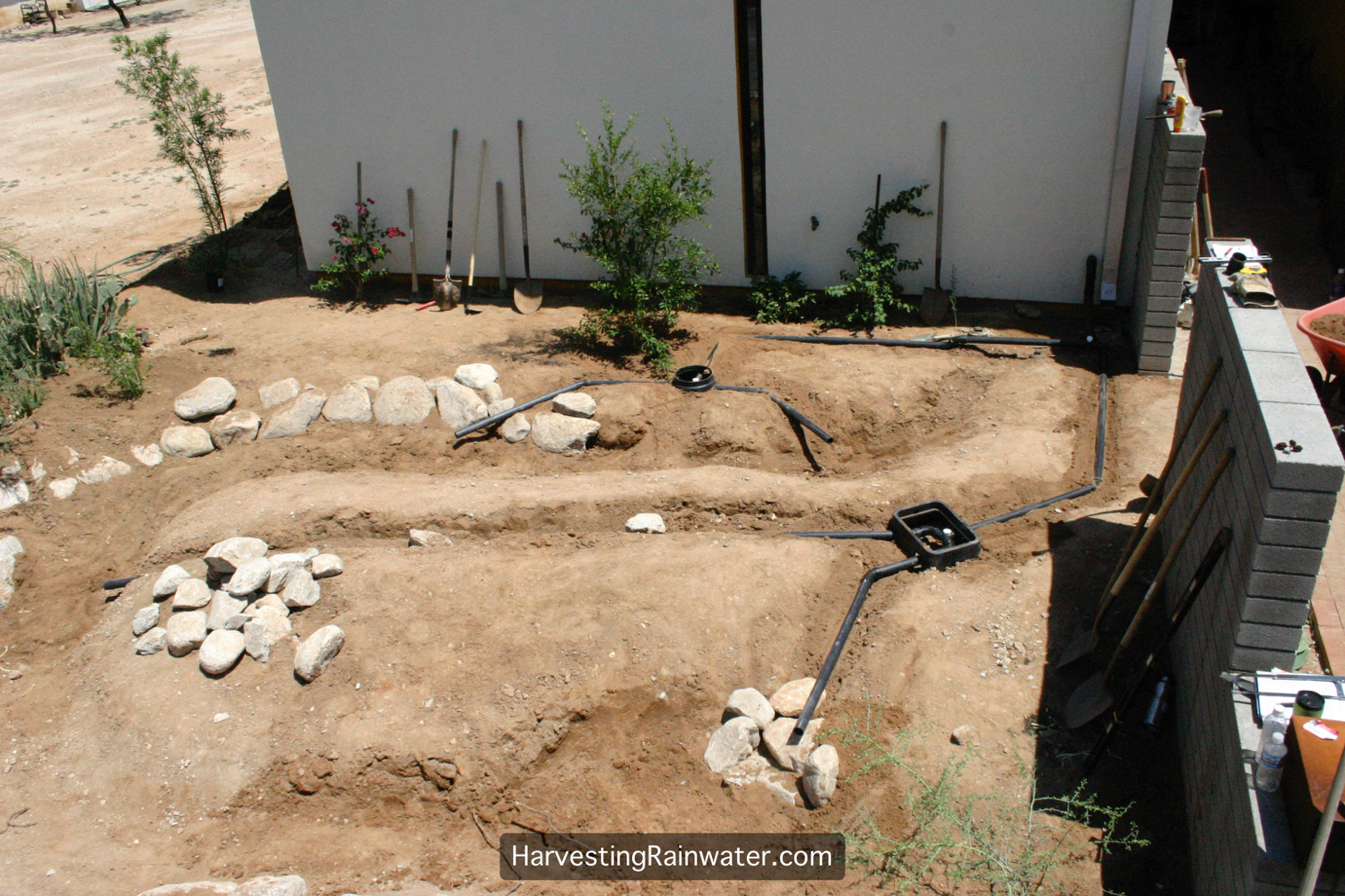
Overhead view of branched-drain plumbing directing household greywater to multiple points within mulched and vegetated basins in the landscape. Flow splitters and underground pipes direct greywater to a total of six outlets. Note: greywater pipe is installed under raised paths to allow easy access and keep the pipe higher in the soil profile. More splits and branches in the flow can be added should the household’s greywater outputs significantly increase. See chapter 12 of Rainwater Harvesting for Drylands and Beyond, Volume 2 for other configurations.
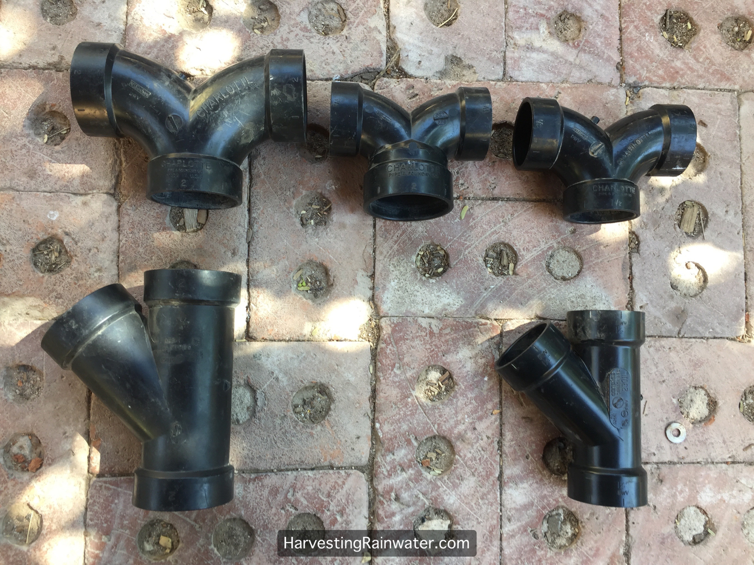
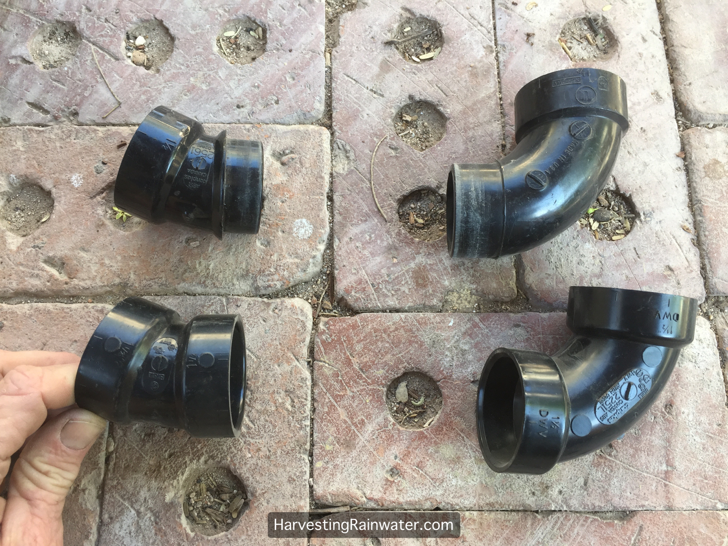
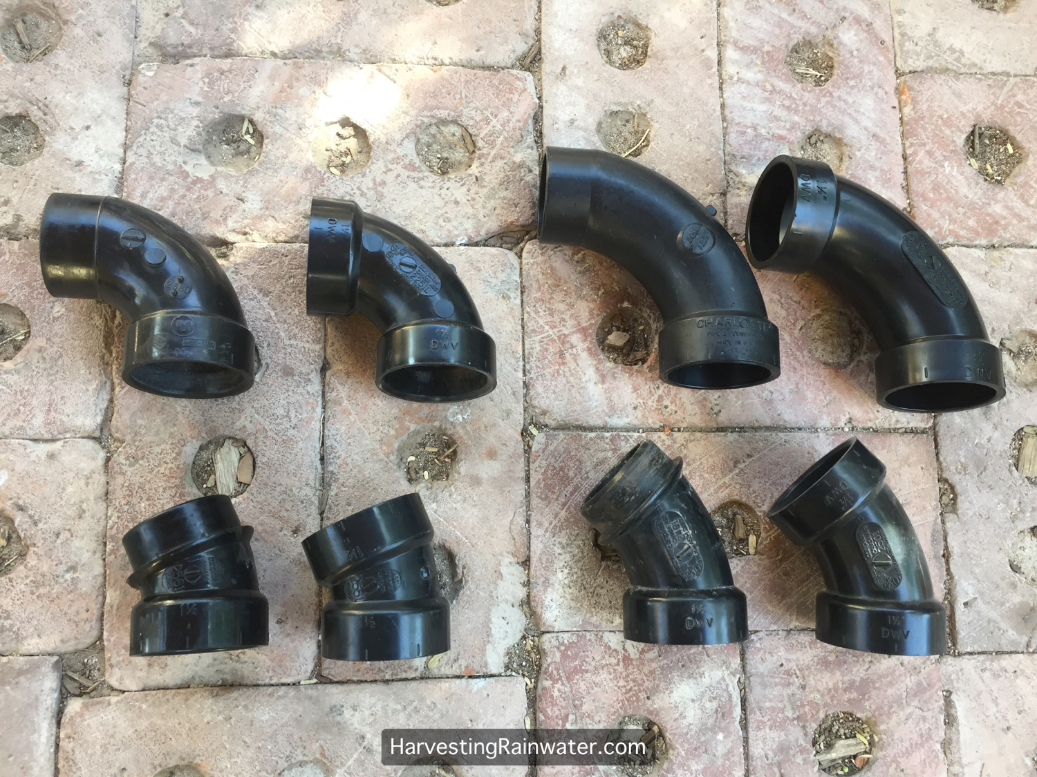
Here are pipe fittings that can be used for flow splitters in a branched-drain system.
Double ells or double bends at top of photo tend to be most reliable at evenly splitting the flow. Ys at bottom. All made of ABS plastic. Available at better plumbing suppliers and OasisDesign.net.
Reduce the amount of plastic you use, waste, and your costs. Once you split the flow from a 2-inch (50-mm) diameter pipe, you can reduce the size of the pipe to 1.5-inch diameter pipe. This will also better move solids in the reduced greywater flow.
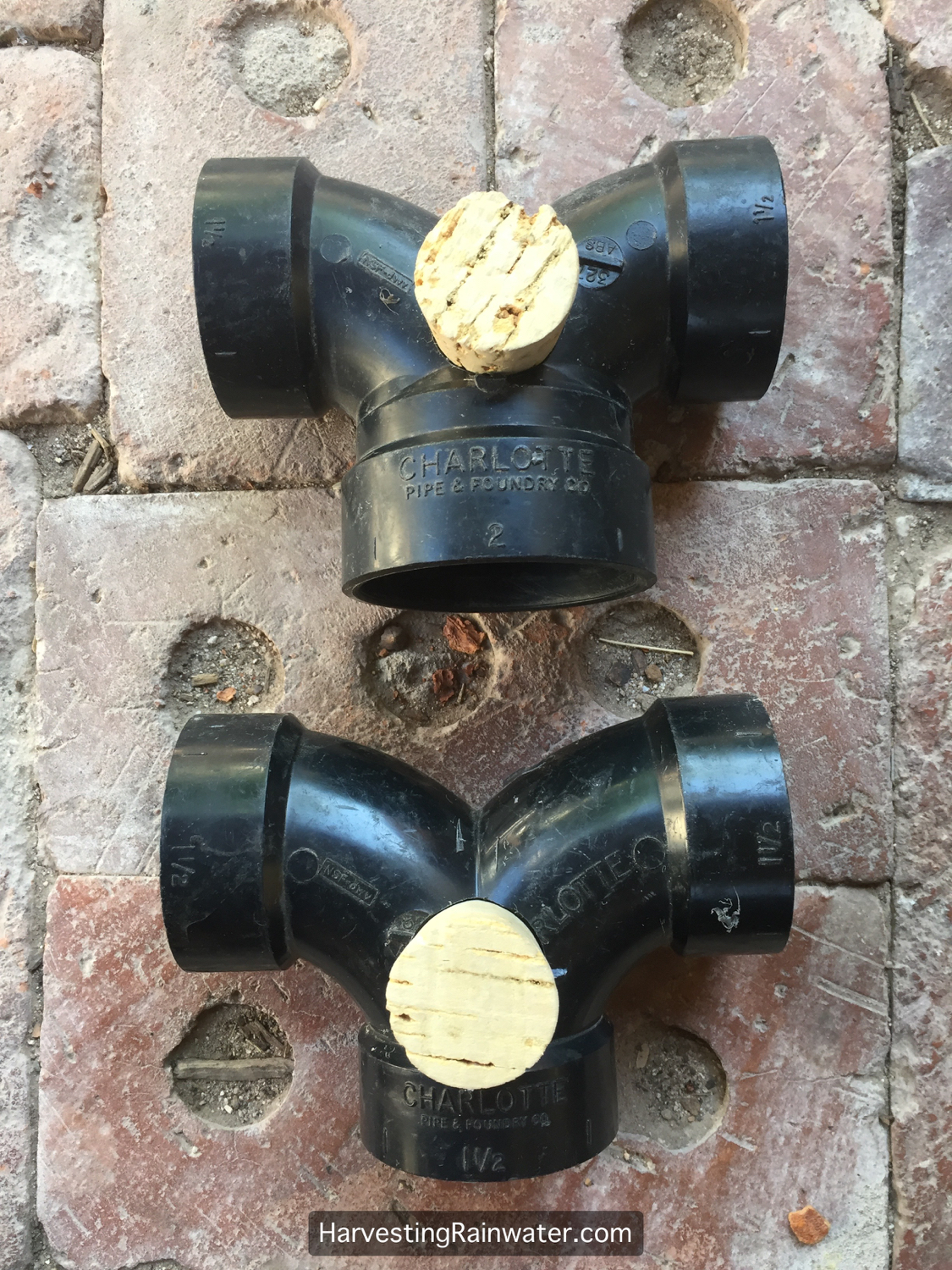
The reduction double ell on top of photo has a 2-inch (50-mm) inlet, and 1.5-inch outlets. 1.5-inch diameter flow splitter on bottom. Both have inspection holes and natural cork plugs added (see How to Make a Flow Splitter with Inspection Hole and Natural-Cork Plug).
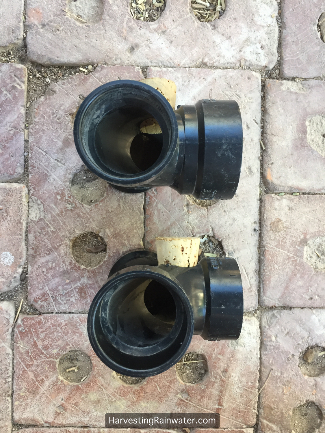
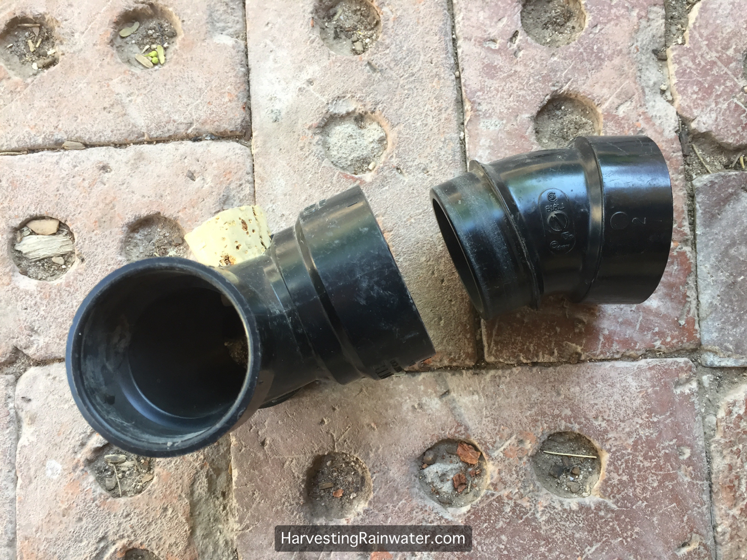
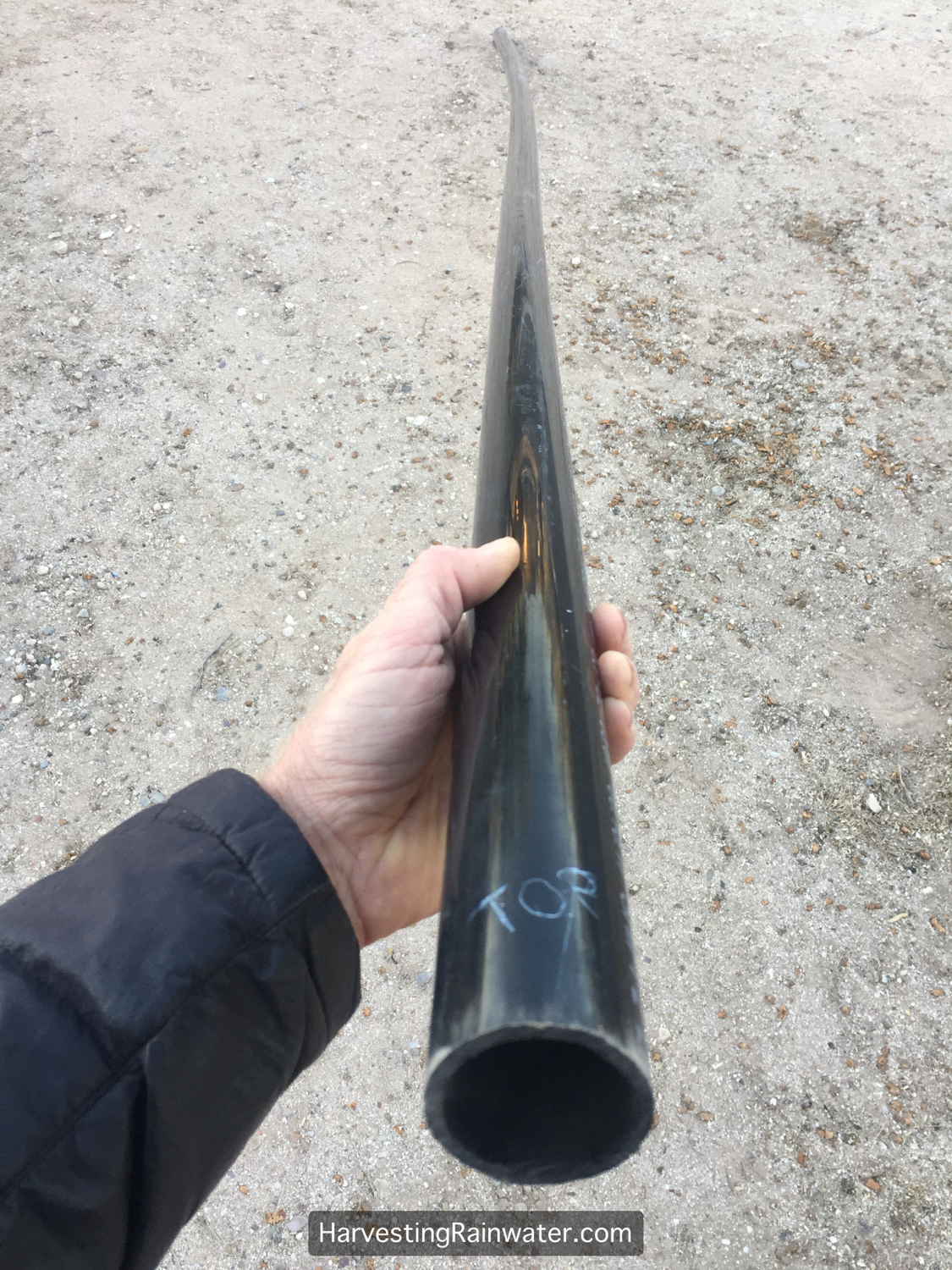
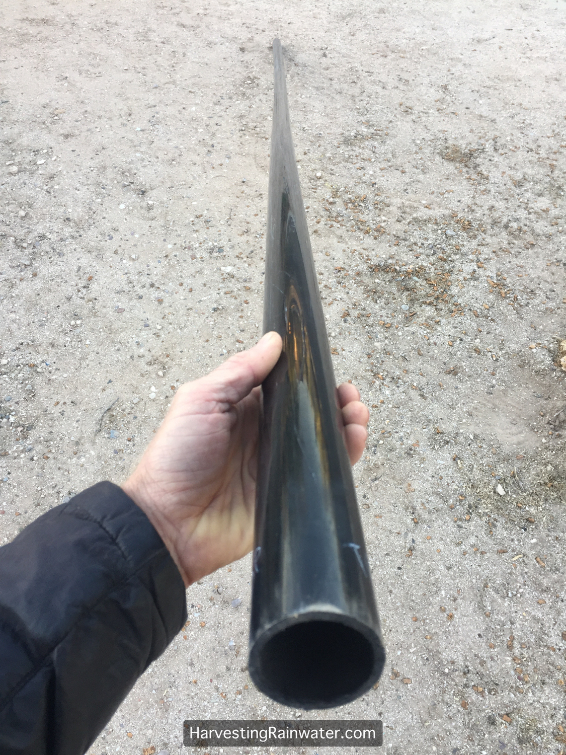
See below for side view of a 2-inch to 1.5-inch double ell flow splitter on top, and a 1.5-inch double ell flow splitter on bottom. Note how the one on the top has a lip or step where the pipe diameter is reduced from 2 inch to 1.5 inch. This can increase the chance for debris build up in the pipe and a potential clog. But there is a simple fix. See next image for another view.
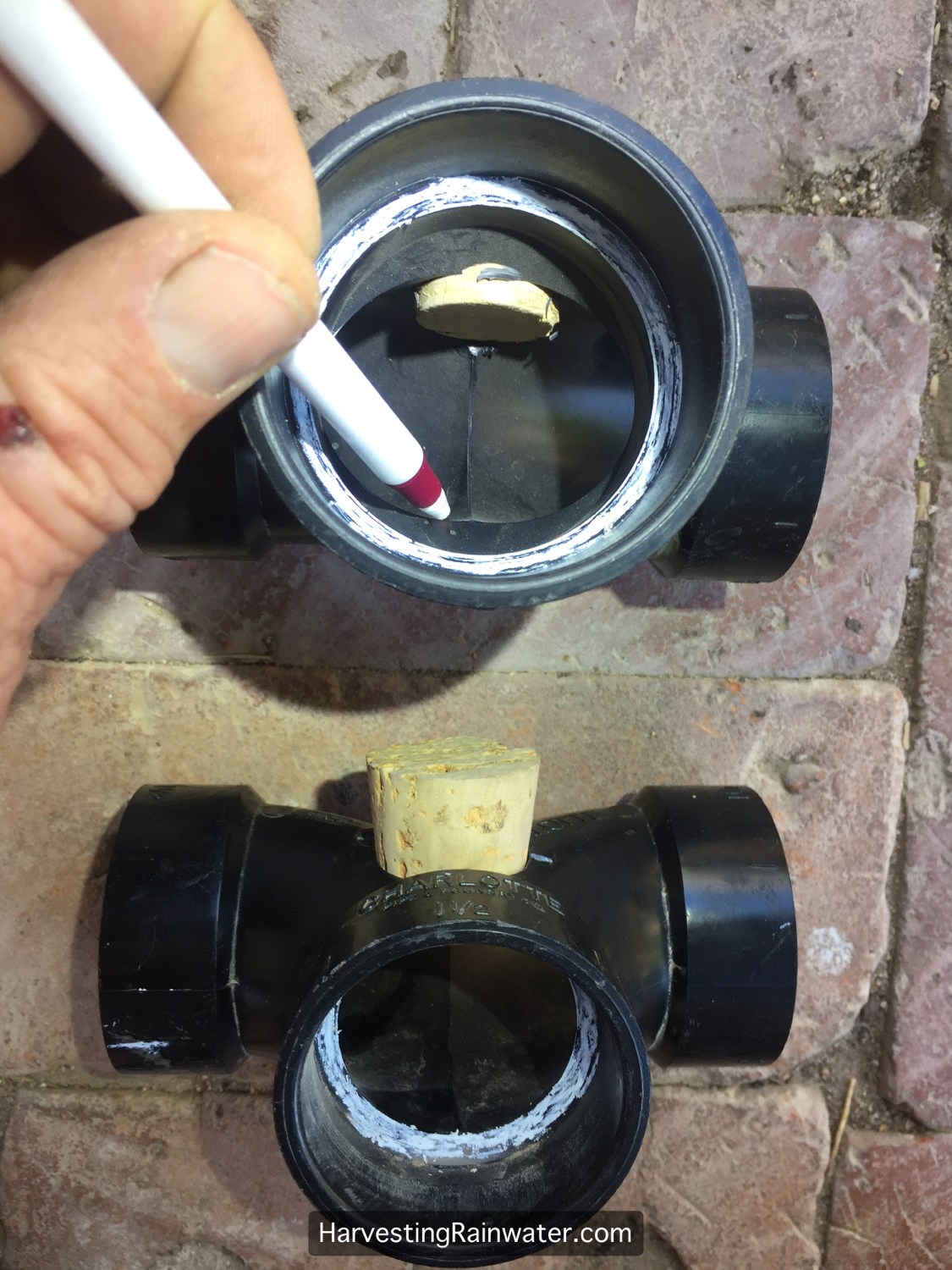
Side view of a 2-inch to 1.5-inch double ell flow splitter on top, and a 1.5-inch double ell flow splitter on bottomLooking inside of the inlet of a 2-inch to 1.5-inch double ell flow splitter on top, and a 1.5-inch double ell flow splitter on bottom. Pen points at lip or step where the pipe diameter is reduced from 2 inch to 1.5 inch. (I colored the pipe white with a wax pencil where the incoming pipe will rest to make the lip, or step, stand out.) This lip or step (present only on the flow splitter that changes its diameter) can increase the chance for debris build up in the pipe and a potential clog. But there is a simple fix – see next image.
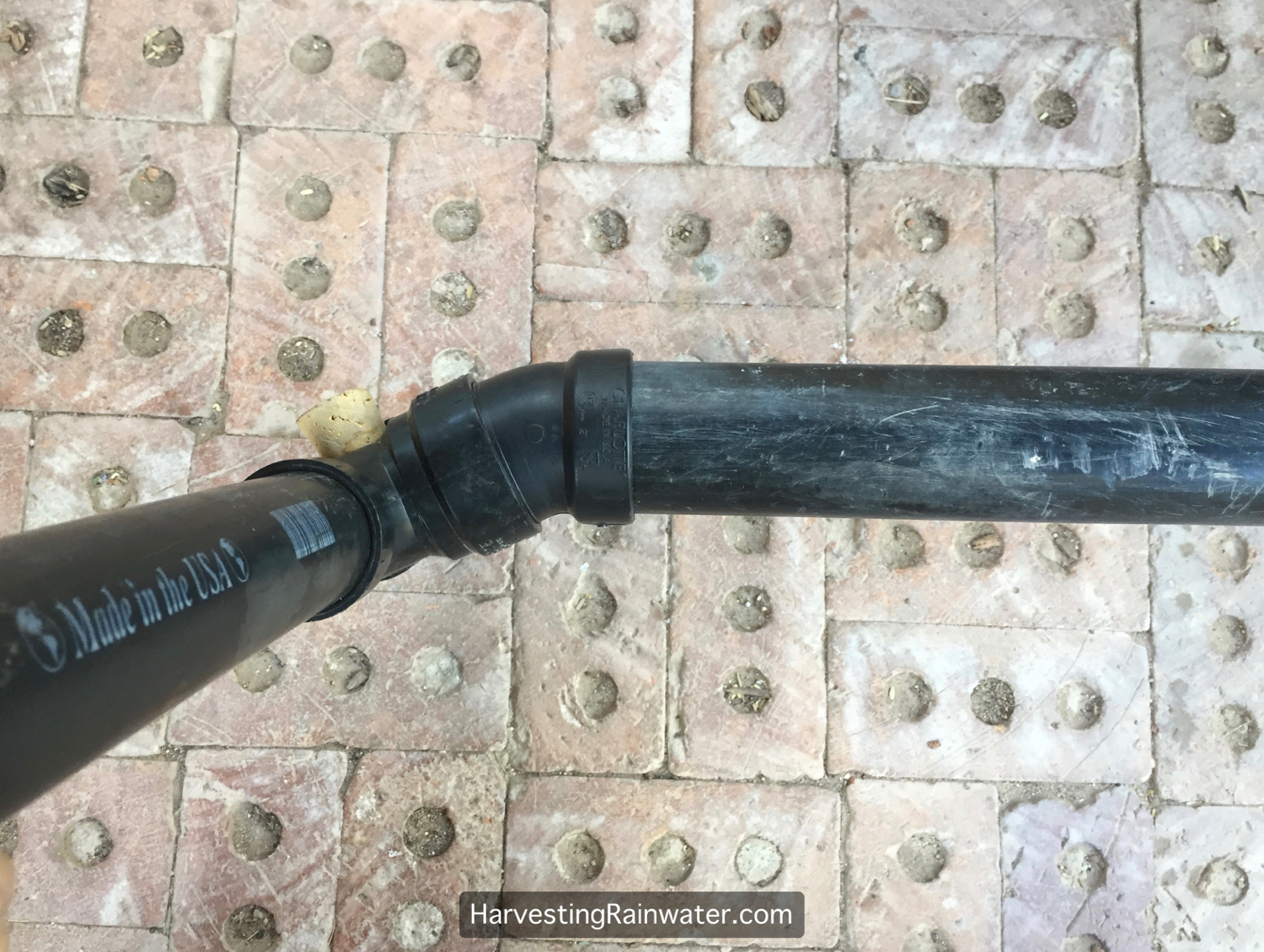
The simple fix:
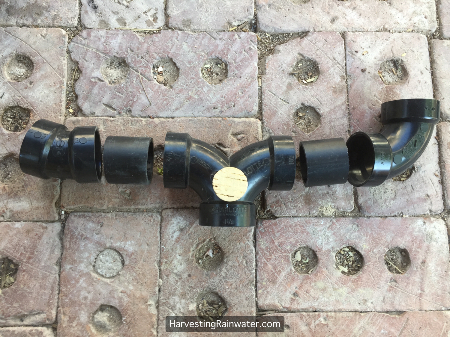
Using a 22-degree street bend just upstream of a 2-inch to 1.5-inch double ell flow splitter creates a waterfall that speeds up the water flow, moving all greywater and debris past the lip or step in the reduction flow splitter.
You don’t need the 22-degree bend in pipe and/or its waterfall effect upstream of a flow splitter that maintains the same diameter of pipe (continuous 1.5-inch diameter pipe for example). It is only needed when you use a reduction flow splitter.
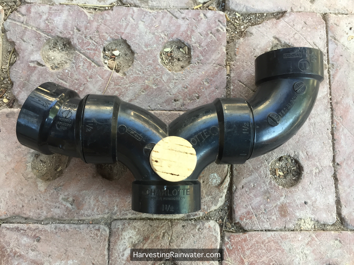
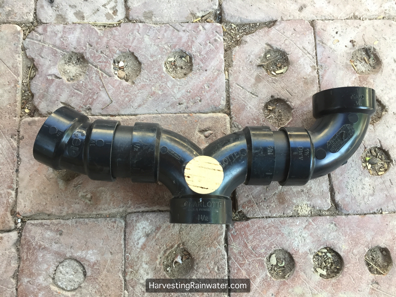
2-inch diameter pipe on right directs greywater into a 2-inch-diameter 22º street bend, then a 2-inch to 1.5-inch double ell flow splitter, then 1.5-inch diameter pipe.
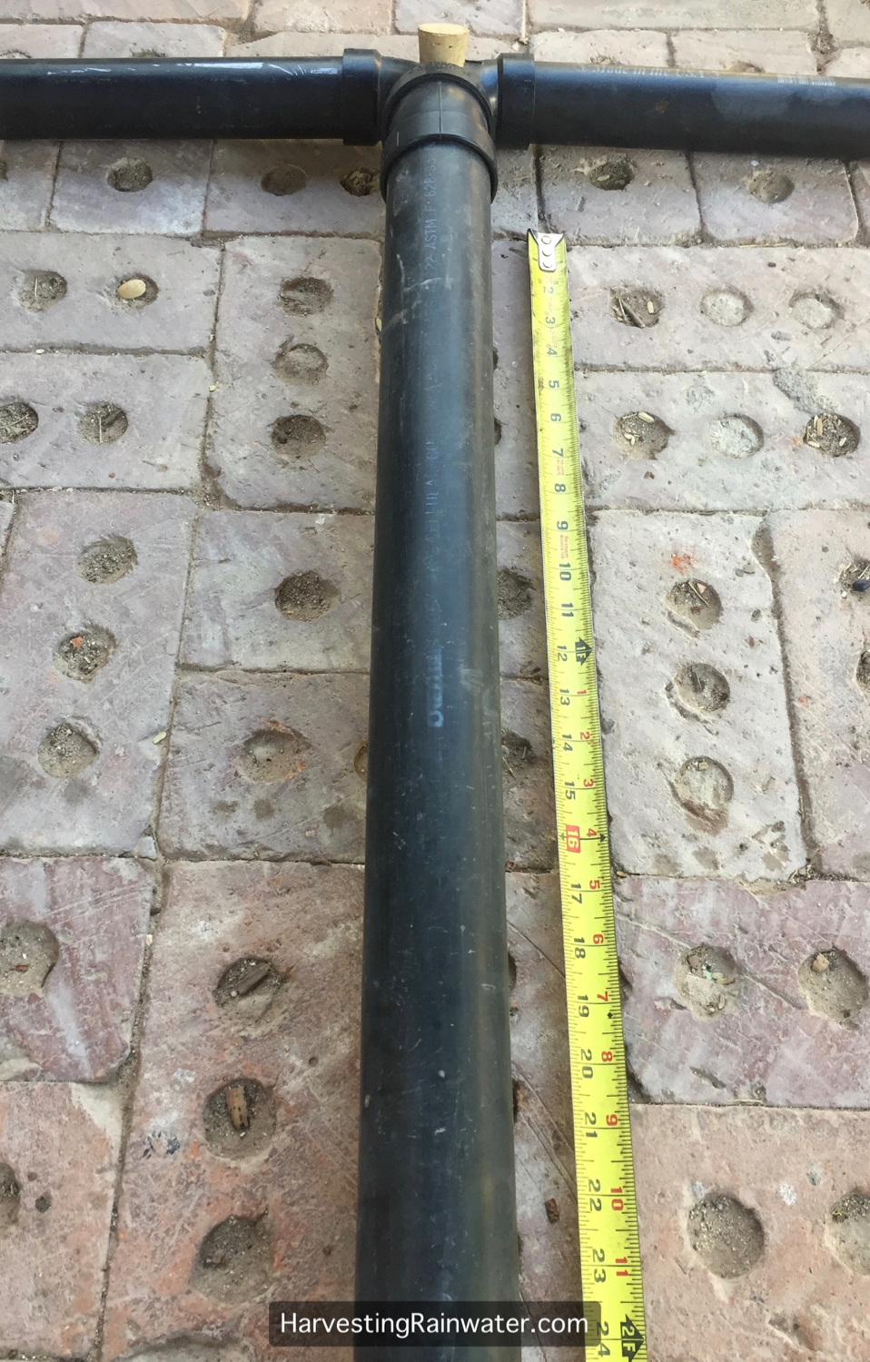
Its good to have at least two feet of straight pipe before you enter a flow splitter to ensure to water flow splits evenly. A side bend in the pipe just before the flow splitter can result in more water going to one side or the other.
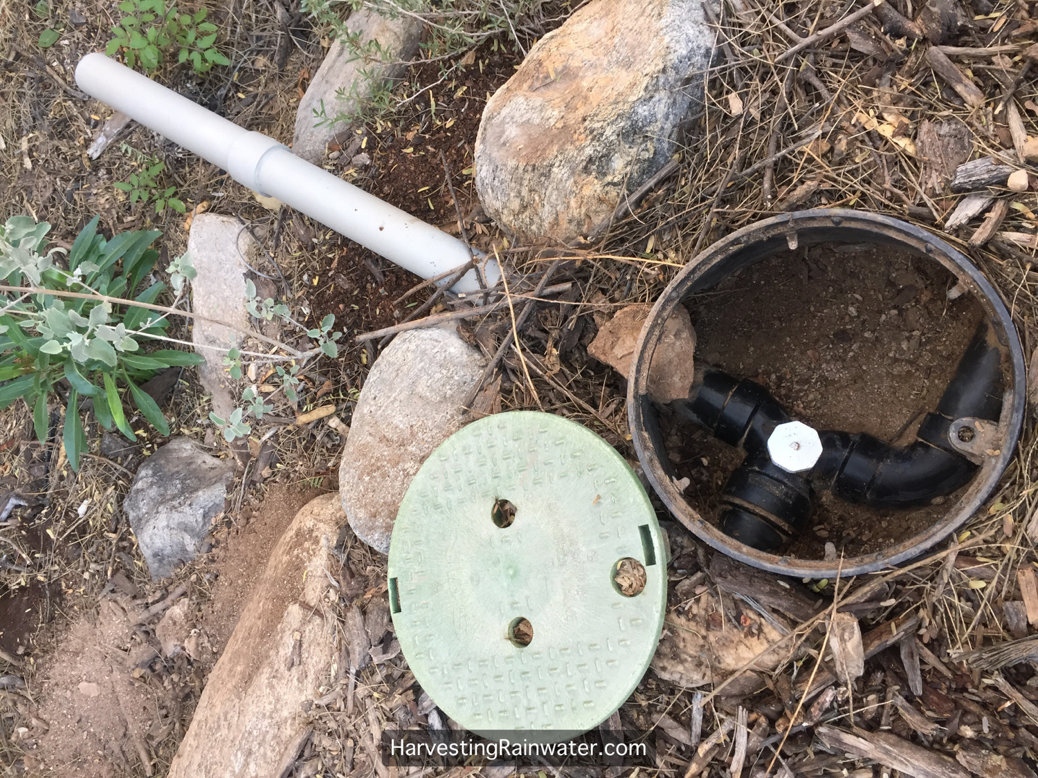
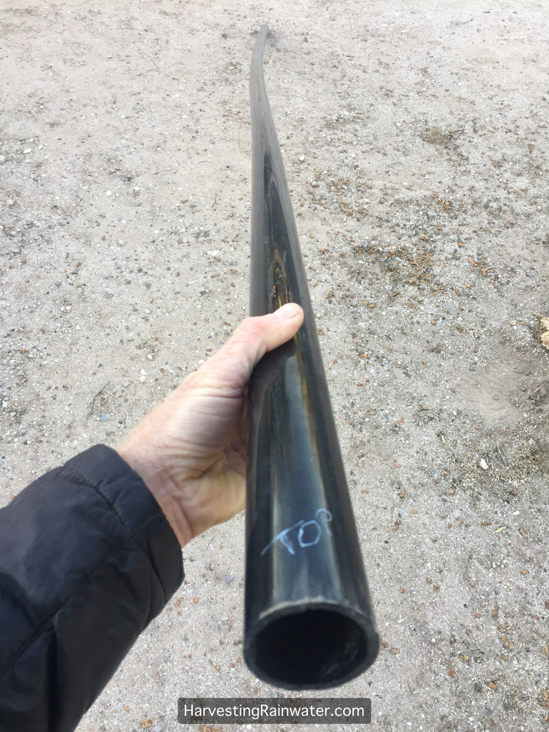
I like to put all my flow splitters where they are accessible so I can easily inspect for—and clean out—clogs (which don’t often occur, but they do happen). If in the ground, I put the flow splitters in valve boxes. Ideally, I like to also have additional pipe bends (if needed) in the valve box so I know what direction the pipe is going once it leaves the valve box. This makes it really easy to know where the pipe is (once its buried) without having to dig it all up.Using street bends makes it easier to fit a flow splitter and pipe bends in a single valve box. Street bends also use less plastic than standard bends.Street bends on top of photo. Standard bends on bottom.Flow splitter with street bends.Flow splitter with standard bends before gluing togetherFlow splitter with standard bends after gluing together. Note how much wider the combined plumbing is compared to the plumbing with street bends two slides prior.Options for pipe bends. Street bends next to standard bends. Starting from top left in a clockwise direction: 90-degree bend, long flush 90-degree bend, 45-degree bend, 22-degree bend. The more gradual the bend the smoother the flow within the pipe, though all these bends work well.Straight runs of plastic pipe typically have a bend in them. So when I install the pipe I make sure the bend is to the side (as is shown here), not up or down (as is shown in the next slide). This is because I’m typically installing the plumbing on flat urban lots, maintaining the minimum ¼-drop in the slope of the pipe; and I don’t want the bend in the pipe to accidentally create a low spot in the pipe run where greywater will pool. So before installing I use a wax pencil to mark what should be the top of the pipe with the bend oriented to one side or the other.Bend in pipe is toward ground in this photo. When I turn the pipe bend will go to the side—see next and previous slides.Pipe turned so bend is to right. Wax pencil used to mark top of pipe with bend going to the side.I try to run pipe in raised pathways so it is always easy to find and access. In addition, it keeps the pipe run higher, so I can have longer runs if necessary, and I can outlet the pipe well above mulched soil.
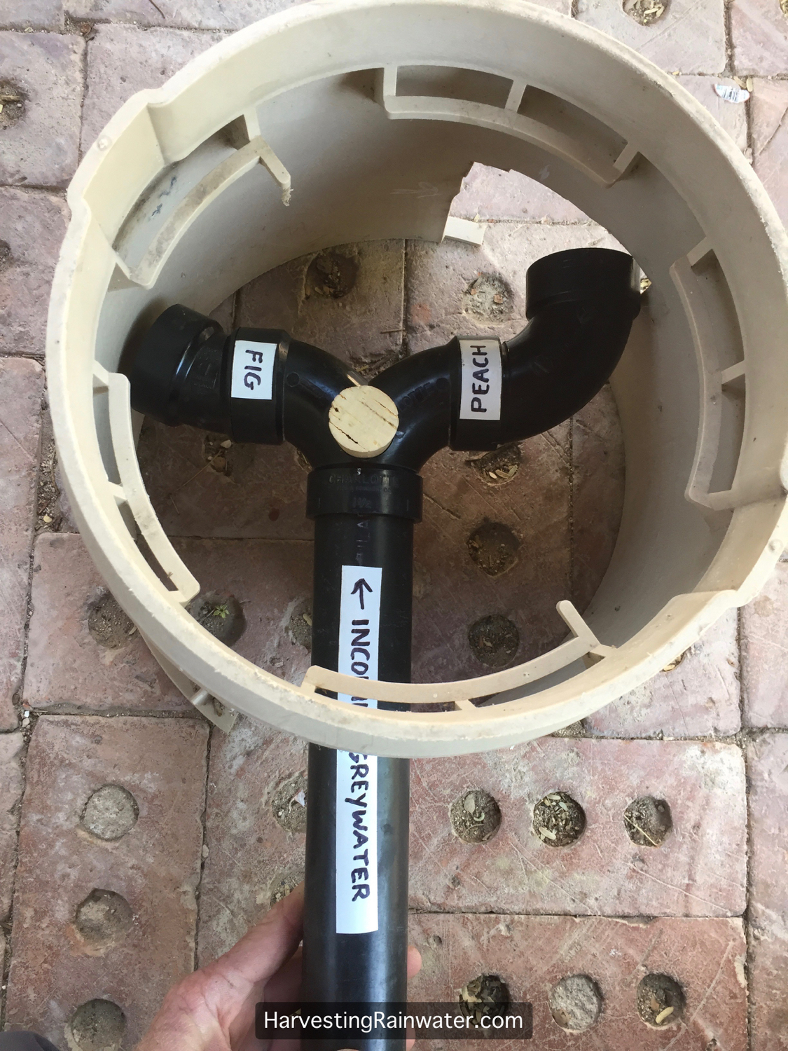
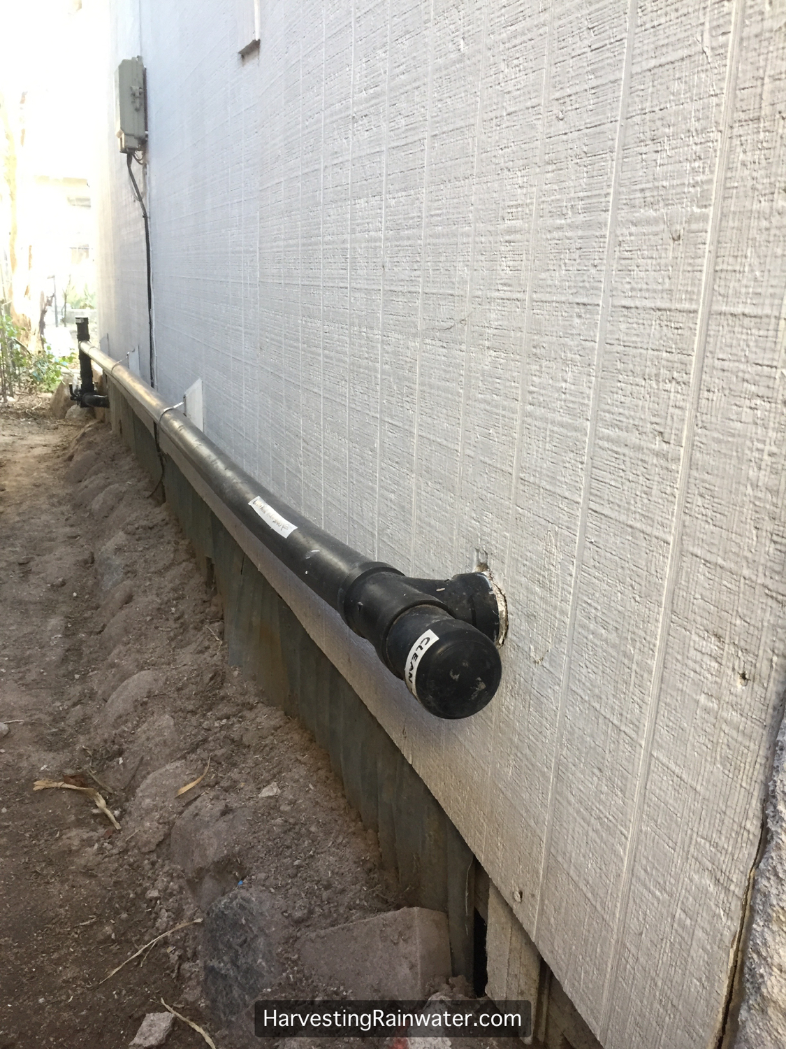
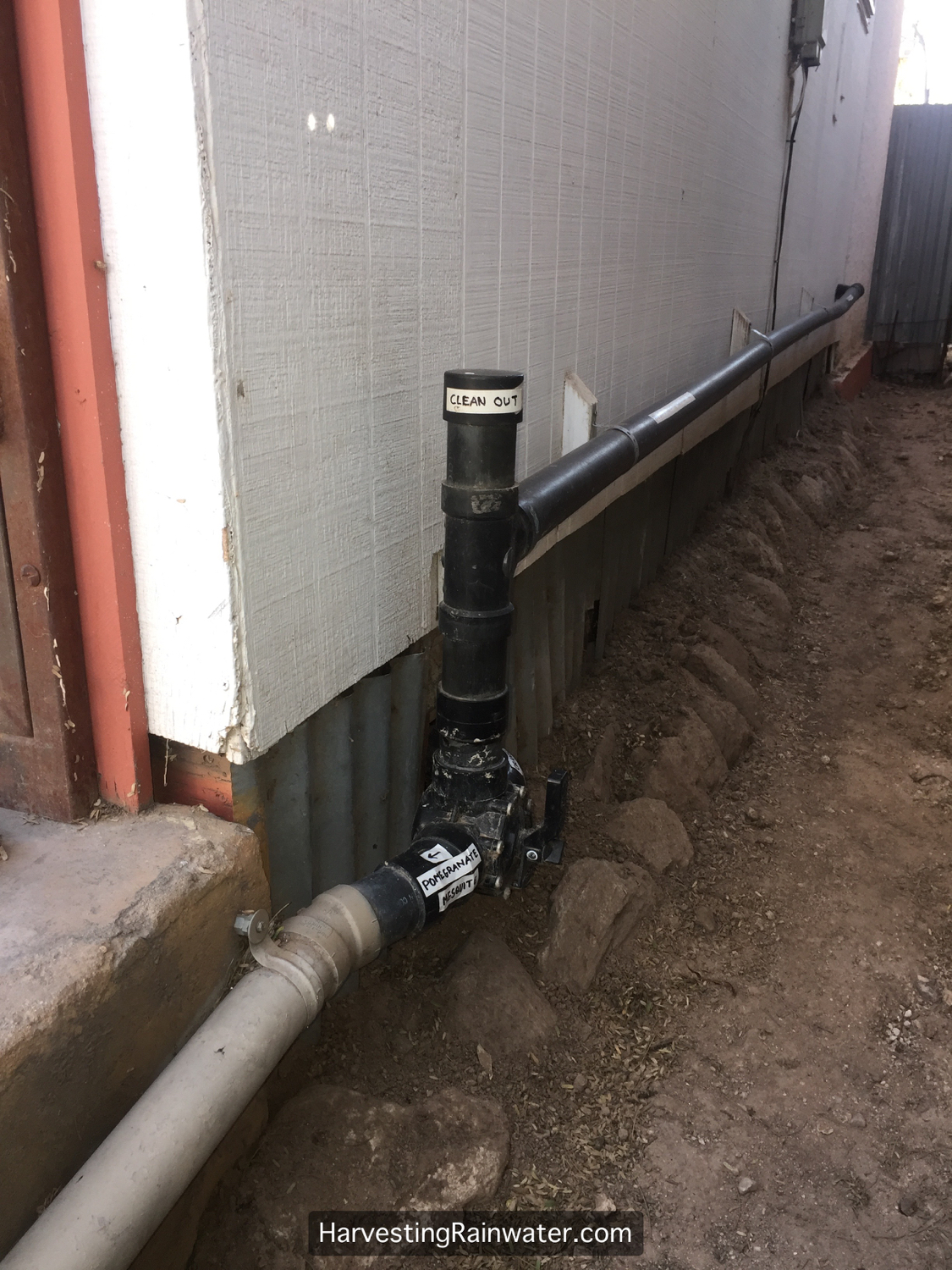
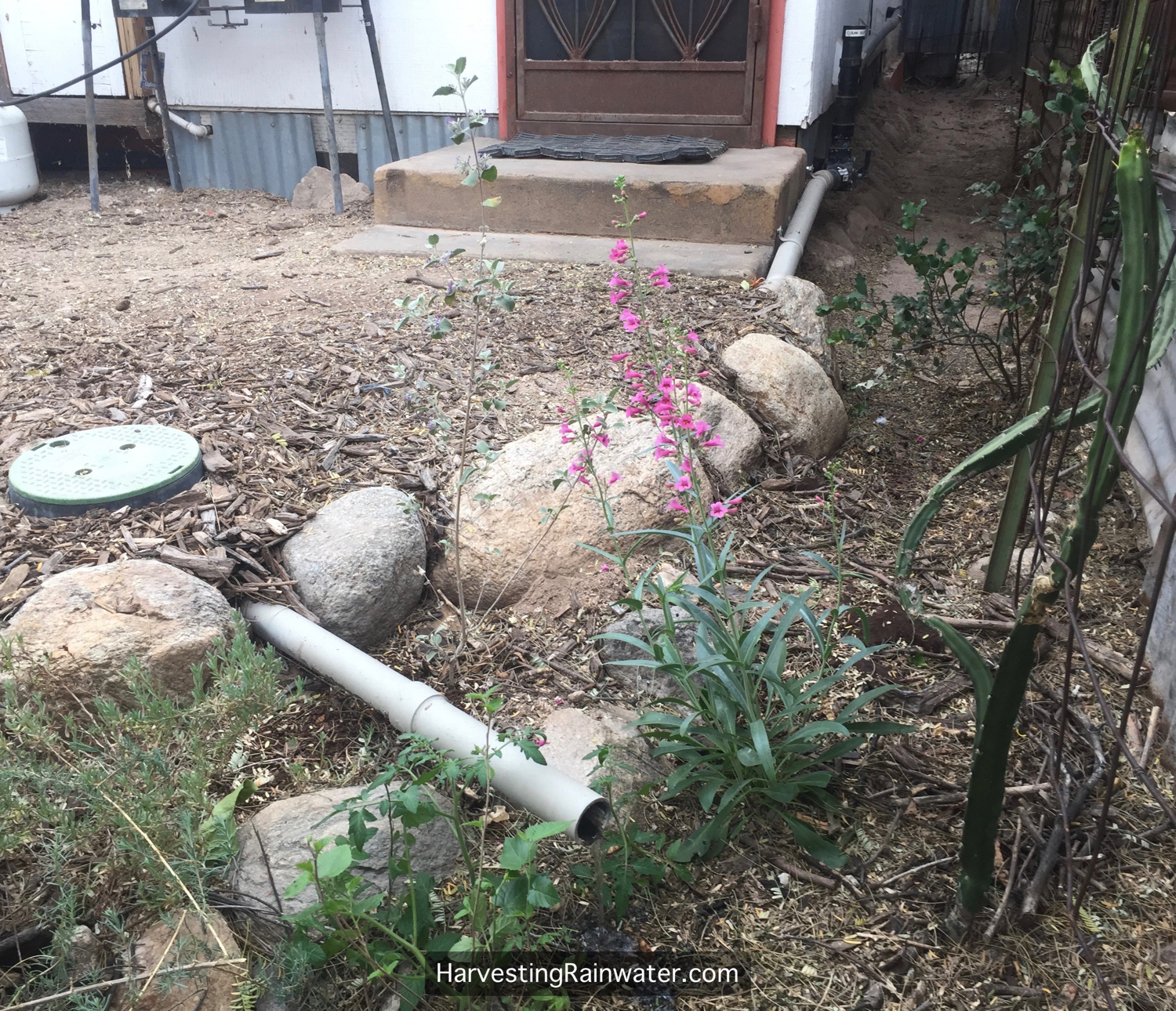
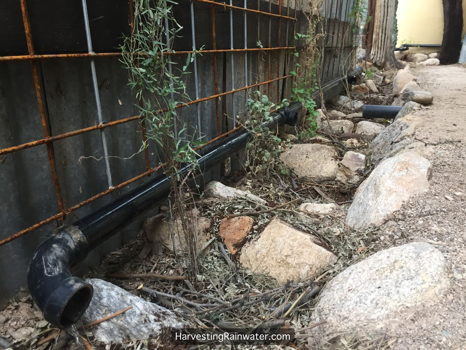
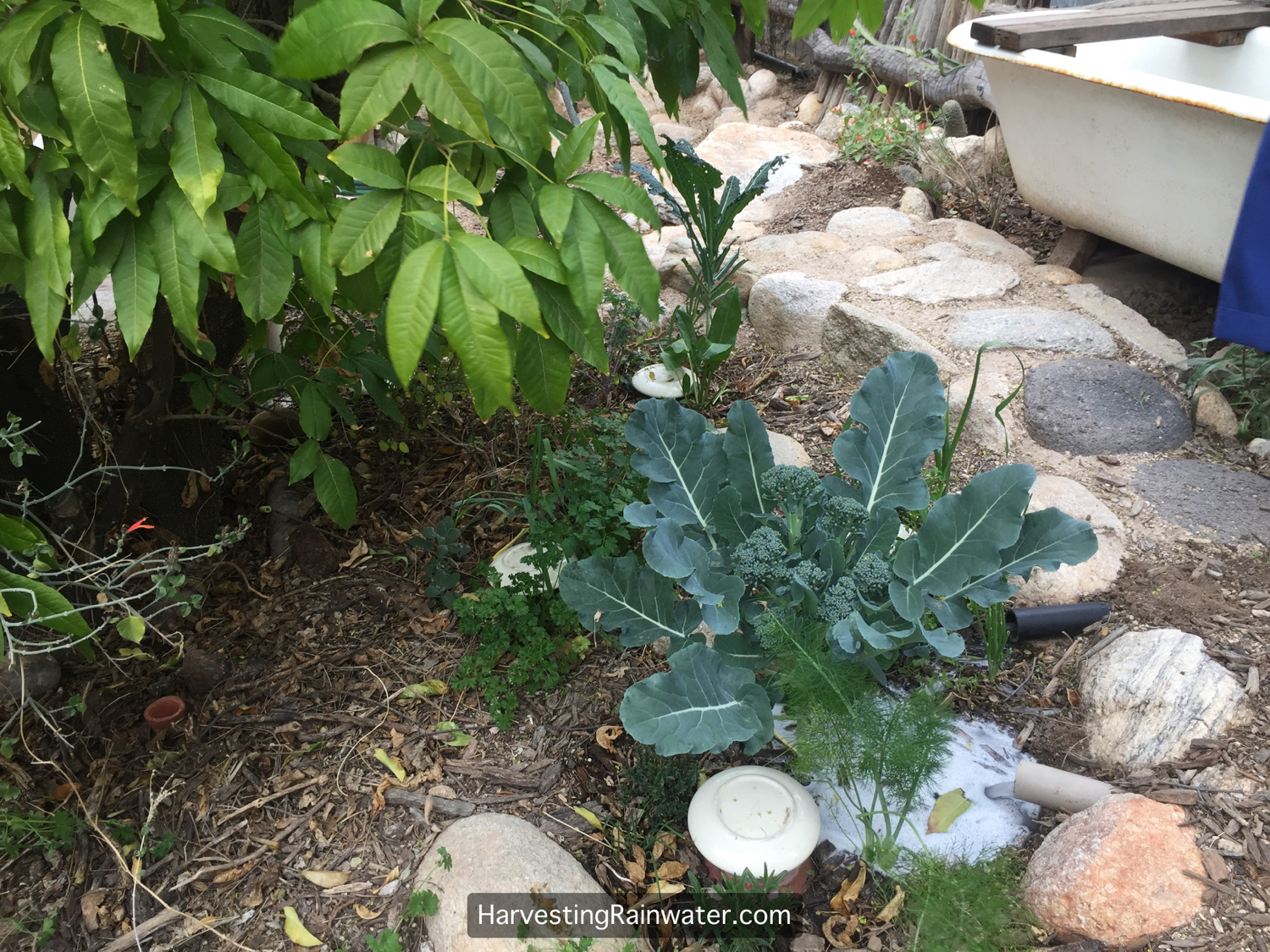
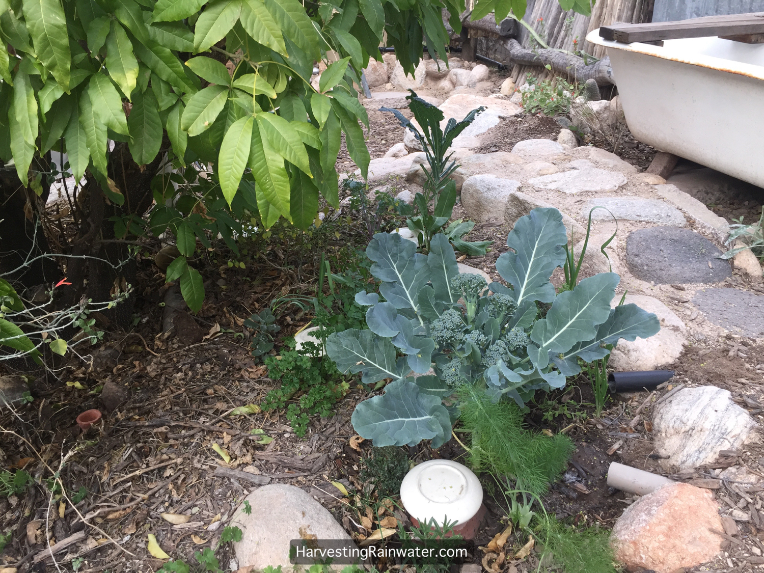
Gravity-fed greywater pipe is kept high, while maintaining a minimum 2% (¼-inch drop per foot) slope, along a wall of a narrow side yard, so the greywater can be distributed further from the house (in larger, planted sections of the yard), and still outlet the pipe above the mulch within a mulched basin. Cap at high end of pipe run is not glued in place so it can function as a clean out access. An improvement would be to bracket the pipe to the wall more often – every 2-3 feet. Paint the pipe when in full sun or where it is desired for aesthetics.Here a three-way diversion valve enables homeowner to direct the greywater to different branches of outlets in one section of the landscape or another. Permanent marker on white electric tape identifies what is irrigated by each pipe run. In hindsight, a much simpler installation would’ve been to just have a double ell flow splitter in place of the 3-way valve, since the valve is typically set to let the flow split evenly into both branched drains anyway. There is already a three-way valve further upstream inside the house, which enables the homeowner to direct the greywater flow either to the landscape or the sewer.One of the greywater outlets from the pipe run in the previous photo. Pipe outlets well above the mulch so there is no possibility of root entry into pipe or clogging. Greywater immediately infiltrates the well-mulched and planted soil. There is a flow splitter in the valve box to the left. A large mesquite tree behind the camera is also irrigated by this greywater outlet.A branched drain greywater system in the air—kept high running along a fence (and wired to a trellis) in order to distribute the greywater from an outdoor sink a greater distance, while still maintaining outlets above the mulch and soil within planting basins. Y flow splitters used here. Note pipe entering a basin from right distributes condensate from a one-room air conditioner.Plant placement in relationship to greywater outlets. Black pipe outlets greywater from outdoor bathtub/shower, while pipe painted tan outlets water from a washing machine. The tree (trunk to left) is the primary perennial plant in the mulched basin utilizing the greywater all year long, while smaller annuals and perennials are planted closer to the greywater outlets so their smaller root systems can utilize the water. The edible parts of all these plants are either cooked before eating or are high enough that the harvested parts never come into direct contact with the greywater—thus all is safe and has served us well for over 20 years.Ten minutes after previous shot was taken, all greywater has infiltrated into the porous, living soil and associated vegetation.Sample site plan showing estimated average annual greywater discharge for a water-conserving household where four people live (based on tables in chapter 12 of Rainwater Harvesting for Drylands and Beyond, Volume 2, 2nd Edition). In addition, annual water needs of trees within easy reach and downslope of household greywater sources are shown. Water needs are based on appendix 4, in Rainwater Harvesting for Drylands and Beyond, Volume 1, 3rd Edition. This way you can estimate what percentage of your plants’ water needs could be met by your on-site greywater. If plants need more water than your greywater can provide, look to supplement their irrigation with other free on-site waters such as rainwater, stormwater, and condensate. If you are not able to meet your plants’ irrigation needs with free on-site waters, consider selecting plants with lower water needs, so your landscape’s irrigation needs are balanced with your free on-site water sources. LW = low-water-use tree, MW = medium-water-use tree, HW = high-water-use tree, D = deciduous (seasonally drops its leaves), E = evergreen, native = native plant
For more
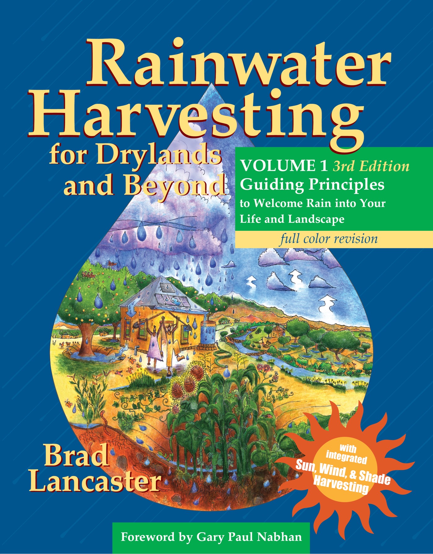
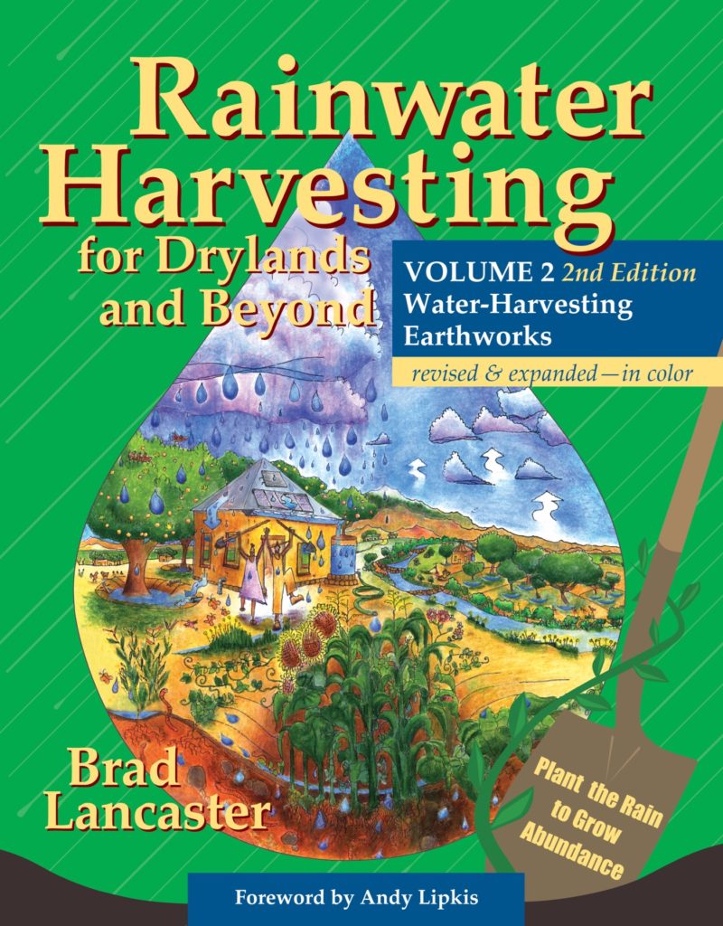
See the new, full-color, revised editions of Brad’s award-winning books
– available a deep discount, direct from Brad:
Volume 1
See appendix 4 to estimate the water needs of your plants, and thus how much of their water needs could be met by your harvested greywater, and other free on-site harvested waters.
Chapter 2 shows you how to estimate your household’s greywater volumes.
See the greywater harvesting chapter and kitchen resource drain (dark greywater water) appendix of this book for how to design and install this and other gravity-fed greywater distribution systems to turn your “waste” waters into free resource waters that can provide you with safe, free irrigation water to grow sustainable abundance where you live, work, and play.